หากคุณต้องการความช่วยเหลือใด ๆ โปรดติดต่อเรา
ภาพรวมโครงการ: เหตุใดถาดเคเบิล U-Channel จึงเป็นโซลูชันเฉพาะทาง
U-Channel Cable Trays are a core component of medium-duty industrial cabling systems , achieving a critical balance between protection, accessibility, and cost-effectiveness. Their semi-enclosed geometry provides continuous, high-integrity support for dense cable bundles, offering better protection against minor mechanical damage and external debris compared to open ladder tray systems.
Engineers favor U-Channel Trays for their predictable mechanical performance , standardized installation processes , and long service life . When environments demand orderly cable segregation and a degree of protection, U-Channel Trays are the preferred choice, widely used in manufacturing facilities, data centers, and specialized machinery rooms.
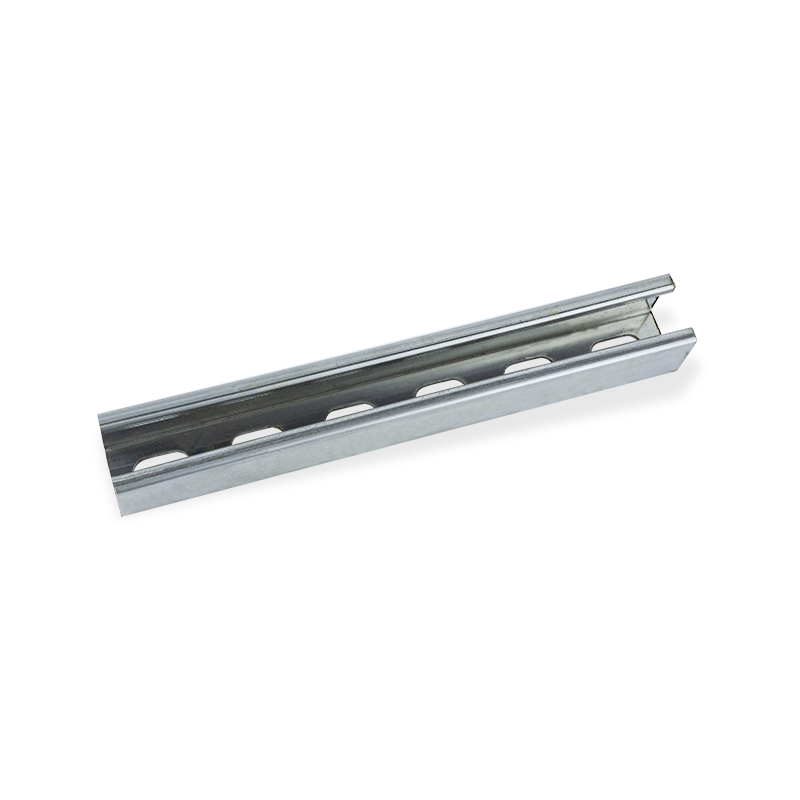
Slotted U channel wire duct cable tray
Structural Mechanics & Material Engineering Considerations
Cross-Sectional Geometry & Load Behavior
The core strength of the U-Channel lies in its cross-sectional geometry . Structural stiffness is proportional to the moment of inertia, and deeper side walls significantly enhance the moment of inertia.
Load & Deflection Control
- A deeper side wall increases the moment of inertia , which minimizes mid-span deflection ($\delta$) under load.
- This reinforcement is crucial for long support spans (exceeding 1.5–2.0 meters) and when carrying heavier power lines .
Material Composition & Finishes (Corrosion Resistance)
Selecting the correct material is crucial for long-term reliability and corrosion resistance :
- Hot-dip galvanized steel: Offers superior corrosion resistance for semi-outdoor or moderately corrosive industrial spaces .
- Stainless steel (304/316): Essential for chemical-heavy , food processing, or coastal environments (high chloride levels).
- Aluminum: Chosen for lightweight installations and excellent strength-to-weight ratio.
- Powder-coated finishes: Used to enhance aesthetics and offer additional protection against humidity .
Thermal Management & Ventilation Optimization
Effective heat dissipation is a design priority to prevent cable insulation aging and system failure.
Heat Dissipation Path Analysis
Because U-Channel Trays are semi-enclosed, airflow is restricted, affecting convection .
- Perforated U channels are highly recommended to maximize convective cooling by increasing the surface area for heat exchange.
Ampacity De-rating
Heat buildup within the tray (the "oven effect" ) necessitates reducing the maximum allowable current (ampacity) for the cables.
- Engineers must apply an ampacity de-rating factor (typically $0.7$ to $0.85$) based on cable fill and ambient temperature.
- Failure to de-rate leads to excessive $I^2R$ heating and compromises long-term cable reliability .
Cable Fill Ratio, Segregation Rules & Pathway Optimization
Fill Ratio Engineering
The Cable Fill Ratio (CFR) dictates the available space within the tray, directly impacting thermal management and accessibility.
- The recommended CFR for U channel trays is generally 40–50% of the available cross-sectional area.
- A lower ratio ensures adequate heat dissipation and provides necessary space for future expansion .
Signal Integrity & Interference Avoidance
Proper segregation is necessary to prevent Electromagnetic Interference (EMI) and ensure signal integrity .
- Divider plates (vertical barriers) must be used to maintain necessary horizontal separation between sensitive communication cables and high-power conductors.
- Isolate high-frequency or high-power cables from sensitive instrumentation or data lines.
Optimizing Cable Run Paths
Efficient routing minimizes cable stress and simplifies installation.
- Minimize sharp turns or unnecessary direction changes.
- Use smooth radius fittings (bends, elbows) for all transitions to prevent cable strain and damage to insulation.
Mechanical Support Design & Span Engineering
Support Spacing Parameters
Support spacing is determined by the calculated load and the material strength of the tray.
- Typical spacing ranges from 1.2 to 3.0 meters .
- Longer spans or environments with significant vibration exposure will necessitate closer spacing or reinforced tray profiles .
Load Calculations Beyond Cable Weight
Robust design uses safety factors to account for all potential loads.
- Static Load: Cable weight, tray weight, and anticipated dust accumulation .
- Dynamic Load: Temporary weight from installation crews or maintenance personnel.
- Environmental Load: Forces from seismic activity or persistent vibration.
- A Safety Factor (SF) of $1.5$ to $2.0$ is mandatory to guarantee system reliability.
Accessory Engineering: Fittings, Joint Stability & Modularity
Elbows, Tees & Transitions
- Use smooth-radius fittings to prevent sharp kinking or crushing of cables.
- Employ vibration-resistant clamps for secure, stable connections.
Joint Reinforcement
Joints are the weakest points in the system and must be reinforced.
- Use thicker-gauge steel connector plates for heavy-load installations.
- Strictly adhere to manufacturer torque specifications when tightening bolts.
Grounding & Bonding
Proper grounding and bonding are safety and electrical necessities for fault current suppression and noise control.
- Install bonding jumpers between adjacent tray sections.
- All grounding points must be clearly labeled and readily accessible for inspection .
Installation Workflow & Engineering Best Practices
Pre-Installation Verification
Thorough planning prevents costly on-site rework.
- Confirm the load-bearing capacity of the structure (walls, ceilings).
- Identify and resolve potential routing conflicts with other building systems.
- Assess maintenance accessibility for future cleaning and inspection *before* installation.
On-Site Alignment & Leveling
Using a laser level for precise alignment is crucial to reduce cable stress and enhance system stability.
Inspection & Long-Term Maintenance
A formal maintenance plan extends service life and ensures safety.
- Annual torque checks on all brackets and connectors.
- Periodic cleaning to remove dust and debris that can impede thermal performance.
- Thermal scanning can be used to non-invasively detect hotspots in power cable bundles.
Selecting the Right U-Channel Cable Tray: Engineering Checklist
| Design Factor | Key Engineering Consideration |
|---|---|
| Load Rating | Evaluate maximum expected load SF of 1.5–2.0 . |
| Environment | Select material (Galvanized, Stainless, Aluminum) based on corrosion and chemical exposure . |
| Thermal Mgmt | Mandate perforated base and apply ampacity de-rating factor ($0.7–0.85$) . |
| Fill Ratio | Maintain 40–50% CFR for thermal and expansion space. |
| Separation | Specify divider plates to isolate sensitive and power cables. |
| Safety | Confirm all sections are grounded and bonded with low-impedance jumpers. |


Youming Group เป็นกลุ่มบริษัทการผลิตที่ดำเนินธุรกิจหลักในการวิจัยและพัฒนาถาดสายเคเบิลความแข็งแรงสูงใหม่
ลิงค์ด่วน
สินค้า
ข้อมูลการติดต่อ
-
No.36, เขตอุตสาหกรรม Taidong เมือง Shiyan, เมือง Dongtai, มณฑลเจียงซู
